Geomechanics Around the World – Series 1
Spotlight on Gulf of Mexico Geomechanics
Cox and Killalea (2010)
While the principles of geomechanics are the same everywhere, the geological and stress environment can result in specific geomechanics concerns for certain parts of the world. In this edition of ERD Magazine, we highlight some of the geomechanics concerns common in the Gulf of Mexico (GOM).
Salt Domes
Salt domes are common in the GOM and due to their proximity to target reservoirs can pose drilling and completion challenges. The following challenges do not represent an exhaustive list but highlight some of the more common issues when drilling in/near salt.
- When drilling through salt, mud properties must be managed to minimize salt creep, which can cause wellbore instability such as tight hole and stuck pipe.
- Stresses in the GOM are typically normal faulting, with vertical stress, SV, being greater than the maximum and minimum horizontal stresses (SHmax and Shmin; SV > SHmax > Shmin). However, stresses re-orient to be parallel and perpendicular to the salt face, which acts as a free surface, so that the principal stresses are no longer vertical and horizontal. Additionally, stress magnitudes can change near salt.
- There is often a salt effect on the resistivity log near salt that can lead to erroneous pore pressure (PP) predictions when using resistivity log-based prediction methods.
- There is typically a large uncertainty in PP and fracture gradient (FG) immediately below salt, in part due to poor seismic resolution and lack of offset well calibration logs.
- Rubble zones at salt exit are common and are typically evidenced by blocky shaped cavings and can cause seepage losses or more severe lost circulation events (Figure 1). Lost circulation materials can be effective at preventing losses, depending on the severity of the rubble zone. Reducing the mud weight (MW) can also help, provided the lower MW is still sufficient to prevent borehole collapse.
- The casing must be able to withstand salt creep with time.
Reactive Shale
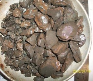
Figure 1: Kumar, et. al (2012), shows blocky and angular shaped cavings.
Shales in the GOM tend to react with water-based mud and can swell which can result in gummy cavings and bit balling. As this is a known issue in the GOM, most operators only use water-based mud in the shallowest hole sections to minimize the potential for drilling problems due to shale reactivity, such as tight hole. If it is not possible to use oil-based mud, the mud properties could be altered to minimize the weakening of the shale. Specifically, mud salinity could be increased to be at least equal to the formation salinity and the membrane efficiency of the mud could be increased.
Narrow Mud Windows
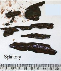
Figure 2: Kumar, et. al (2012), shows splintery shaped cavings.
Many areas of the GOM have high overpressure, especially at depth, which requires careful planning. Mud windows can become very narrow when overpressure is high, especially considering new government regulations, but insufficient MW will cause the rock to break off the wellbore wall in splintery shapes (Figure 2). When splintery shaped cavings are observed, it is a good indication to increase your MW, provided there is room in the mud window to do so. New regulations which may further reduce MW window may require more advanced techniques and equipment to drill successfully, such as Managed Pressure Drilling (MPD).
Weak Bedding
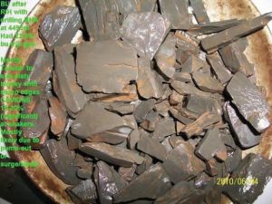
Figure 3: Kumar, et. al (2012), shows platy and splintery shaped cavings.
Weak bedding planes have also been observed in the GOM. When there is low cohesion or a low coefficient of friction between beds, drilling at low angles with respect to beds can become unstable and require higher MW to maintain stability. Note that if beds have no cohesion, increasing the MW can actually exacerbate the instability by encouraging mud penetration between the bedding planes. Lost circulation materials can be used to help prevent mud from penetrating between the bedding planes. Drilling perpendicular to bedding is most stable, but is not always possible given trajectory constraints. Weak bedding is evidenced by platy shaped cavings (Figure 3). Drilling problems most often associated with splintery and platy shaped cavings are tight hole, pack-off and stuck pipe. A summary of cavings shapes and recommended actions is shown in Table 1.
Table 1: Cavings Shape vs. Typical Recommended Action
| Caving Shape | Typical Recommended Action |
| Gummy | Change mud type; Alter mud properties (increase mud salinity and/or improve membrane efficiency) |
| Blocky | Utilize lost circulation materials; Reduce MW provided the new lower MW is still sufficient to prevent borehole collapse |
| Splintery | Increase MW, provided there is room in mud window to do so |
| Platy | Increase MW*; Change trajectory to hit beds at a higher angle (drilling perpendicular to beds is most stable); Utilize lost circulation materials |
*Note that if beds have no cohesion, increasing the MW can actually exacerbate the instability by encouraging mud penetration between the bedding planes.
Time Dependency
It is important to understand that all wellbore instability is time dependent! Wellbore failure worsens with exposure time. This time dependency can be manifested in several ways. In some cases, there will be an initial indication of wellbore instability from cavings that will gradually worsen with time, despite efforts to correct the problem by varying mud properties. In other cases, there will be no initial indication of wellbore instability, but after the wellbore wall is exposed for a day or two, instability occurs. This delayed instability is probably most common in the case of creeping salt and reactive shale but can also occur in the presence of weak bedding planes, when there is time dependent mud penetration between the beds. Time dependent instability can even occur when there is no triggering geomechanical problem, due to fatigue of the rock after repeated trips, for example. It is important to plan a drilling program carefully to minimize exposure time and thus, instability.
Pressure Differential
There is also often a pressure differential between sand and shale. As a result of centroid and buoyancy effects, you can drill into a sand body that is at a higher or lower pressure than the background shale pressure, depending on where you enter the structure. The sand pressure will be higher than the background shale pressure if you drill into the sand above its center of mass and will be lower than the background shale pressure if drill into it below its center of mass. Sands can also have low pressure from depletion.
Minimizing Risk
While it is obvious it is very important to plan GOM wells carefully, pre-drill predictions will always have some inherent uncertainties. Many pre-drill PPFG models in the GOM rely primarily on seismic velocity, which does not always match actual well logs, depending on seismic resolution, processing and general quality. Additionally, relying only on seismic data makes it very difficult to calculate the high-resolution borehole collapse pressure (CP), which takes into account the PP and stresses, rock properties, well trajectory and allowable breakout/failure width. CP should be considered along with the PP when determining the lower bound of the mud window. Note that a 1D elastic model does not apply in salt and traditional salt management techniques must be used when drilling the salt interval, such as using a MW with density close to SV and salinity at or near saturation. Lost circulation materials and/or a lower MW may be required right below the salt if a rubble zone is encountered. Any potential permeable zones below salt should also be considered when designing the casing plan.
Figures 4A and 4B illustrate the importance of CP in well planning. In Figure 4A, we show a stereonet at a certain depth of CP for any well trajectory for a representative GOM well with PP = 14.7 ppg. The CP for a vertical well is 15.1 ppg, 0.5 ppg above the PP. Considering only the PP when determining the minimum safe MW to use could result in wellbore instability while drilling. Figure 4B shows a stereonet at the same depth of CP for the same representative GOM well with the addition of weak bedding planes. The beds dip 30 deg with a dip azimuth of 90 deg and have 300 psi of cohesion and a friction coefficient of 0.4. To see the impact of the presence of weak bedding on the CP simply compare the CP for wells drilled at high angles with respect to beds, with and without weak bedding. For example, a 60 deg deviated well drilled to the east has a CP of ~15.8 ppg with weak beds and ~15.3 ppg without weak beds. A lateral well drilled to the north or south has a CP of ~16.2 ppg with weak beds and ~15.5 ppg without. Not accounting for the presence of weak beds can result in severe wellbore instability.
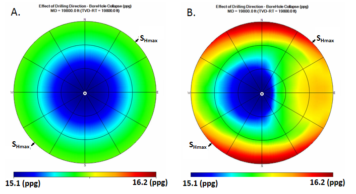
Figure 4A. Stereonet at a certain depth shows the borehole collapse pressure (CP) for any well trajectory for a representative GOM well with PP = 14.7 ppg. Vertical wells plot in the center and horizontal wells plot along the edge. The allowable breakout width is 90 deg for a vertical well and 30 deg for a horizontal well. Figure 4B Shows the CP for the same representative GOM well at the same depth with the addition of weak bedding planes. The beds dip 30 deg with a dip azimuth of 90 deg and have 300 psi of cohesion and a friction coefficient of 0.4. The allowable failure width (the summed width of the breakout of isotropic rock and anisotropic failure from the beds) is 90 deg for a vertical well and 30 deg for a horizontal well.
As previously mentioned, there are inherent uncertainties in any pre-drill model. There is also a need to respond rapidly to any wellbore instability event that occurs while drilling to minimize non-productive time and prevent a small incident from developing into a large, or even catastrophic, incident. It is the position of HXR Drilling Services that it is best practice in any high pressure, high-angle, or potentially complex area to combine a thorough pre-drill geomechanical model with real-time monitoring services. Please contact us for further information on how we can use our unique combination of drilling and geomechanics expertise to help you optimize your drilling plan, minimize exposure time and instability, and maximize your chances of a successful wellbore.
References and Further Reading
Aadnoy, B.S. and M.E. Chenevert, 1987. Stability of highly inclined boreholes. SPE Drilling Eng., 2 (4), pp. 364–374.
Cox, M. and Killalea, M., 2010. Technological advances enable companies to overcome challenges of drilling through salt. Drilling Contractor, May/June 2010. Available on www.DrillingContractor.org.
Dickinson, G., 1953. Geological aspects of abnormal reservoir pressures in Gulf Coast Louisiana. American Association of Petroleum Geologists Bulletin, 37: 410 – 432.
Finkbeiner, T., Zoback, M., Flemings, P., and B. Stump, 2001. Stress, pore pressure and dynamically-constrained hydrocarbon column heights in the south Eugene Island, Gulf of Mexico. American Association of Petroleum Geologists Bulletin, 85(June), 1007–1031.
Kumar, D., Ansari, S., Wang, S., YiMing, J., Ahmed, S., Povstyanova, M. and B. Tichelaar, 2012. Real-time Wellbore Stability Analysis: An Observation from Cavings at Shale Shakers: Search and Discovery Article #41095 (2012). Website accessed Posted December 10, 2012. http://www.searchanddiscovery.com/pdfz/documents/2012/41095kumar/ndx_kumar.pdf.html
Traugott, M. O. and P.D. Heppard, 1994. Prediction of pore pressure before and after drilling – taking the risk out of drilling overpressured prospects. AAPG Hedberg Research Conference, American Association of Petroleum Geologists.
Willson, S.M., N.C. Last, M.D. Zoback, and D. Moos, 1999, Drilling in South America: A wellbore stability approach for complex geologic conditions: Paper SPE 53940-MS presented at Latin America and Caribbean Petroleum Engineering Conference. Caracas, Venezuela. 21−23 April. DOI: http://dx.doi.org/10.2118/53940-MS.
Zoback, M., 2007, Reservoir Geomechanics, First Edition: Cambridge University Press. 452pp.