P&A Success
HXR Successfully Plug & Abandons Legacy Wells at Barrow, Alaska
Members of HXR’s Alaska Project Management Team, Dan Shearer, Nick Scales and Tom McKay, were able to successfully design and engineer the plugging and abandonment of 1940s’ legacy wells at Barrow Alaska.
HXR was able to successfully design, engineer, supply and assemble an efficient, affordable and complete P & A package to their customer at the northernmost tip of Barrow, Alaska.
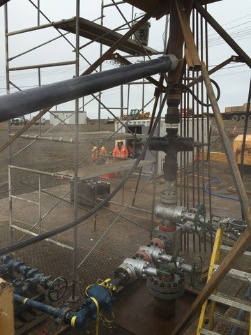
BOP stack and work platform designed by the HXR Engineering Team.
Story…
This summer, HXR successfully plugged and abandoned 3 legacy wells from the 1940’s at Barrow, Alaska for the U.S. Bureau of Land Management. The city of Barrow (an Inupiat whaling village) is the northernmost city in the United States, located on the Arctic Ocean north of the Arctic Circle. It has been home to the Native Inupiat Eskimo people for over 1,000 years and many still reside there, making up over half of the population. It is the largest of the many remote villages in Alaska, not accessible by roadways. Because Barrow is north of the Arctic Circle the sun does not rise for several winter months, nor set for several summer months. It has the coldest average temperatures, some years experiencing snow every month of the year. Due to the short Arctic summer barging season (~6 weeks), it was critical that all equipment, products, parts and pieces needed for the P&A project arrive at location in a very short window of opportunity. Unknown factors such as winds, sea ice, whaling season and cultural events dictate when the barges can and cannot come into shore.
The History:
In the late 1940s’ (Post WWII), the U.S. Navy was searching the Naval Petroleum Reserve, Alaska (N.P.R.A.) for a northern, petroleum hydrocarbon source on the Western part of the North Slope of Alaska. A large area was observed to contain multiple oil seeps which had accumulated into small ponds in low lying areas. These accumulations were confirmed in areas, that in 1940’s travel were considered vast distances from Barrow. Multiple wells were drilled across the Western North Slope by the U.S. Navy, and very few were properly plugged and abandoned by today’s standards. Researching these wells was very interesting and complex as most of the reports were written in pencil and have long faded to grey.
The Request:
Plug and abandon, then remediate three wells and two rat-holes near Barrow, Alaska.
Comply with:
- Regulatory requirements of the U.S. Bureau of Land Management (BLM) and the North Slope Borough.
- All abandonment criteria set out in 43 CFR 3160 Onshore Oil and Gas Order No. 2.
- Apply and receive BLM Sundry Notice Approvals
- U.S. Army Corps of Engineers (USACE) Jurisdictional Determination
- North Slope Borough (NSB) Admin. Approval and Traditional Land Use Inventory/Cultural Clearance (TLUI)
- State Historic Preservation Office (SHPO) section 106 Historic Preservation Authorization
- Alaska Department of Fish and Game (ADF&G) Title 16 Fish Habitat Permit & Public Safety Permit
- Land access authorization
- Roadway shared use agreements, as needed
HXR’s challenge:
- Design, engineer, equip and direct 3 remote well P & A’s and 2 Rat-Hole remediation in the Arctic.
- Research and network for any trace of readable, relevant well files.
- Design and engineer three (3) wellhead adaptor systems to allow each well a separate nipple up.
- Design and verify work string and tubular criteria.
- Design and test, cement header and BOP test manifold
- Design cost effective, BLM acceptable, small, lightweight, efficient BOPE stack and BOPE system.
- Design cost effective, stable, lightweight work platform with a false table and bell nipple/flowline system to pits.
- Design circulation and safety valve systems.
- Equip well project through vendor interviews and bids.
- Design circulation fluids per BLM criteria.
- Engineer contingency plan to deal with Thermistor cables or Barite sag.
- Develop Well activity produced, solids, liquids, liquid volumes and type estimates (DEC).
- Engineer an Arctic design cement slurry for maximum 12 hour/500 psi compression test ability.
- Remediate wellhead and surrounding areas per BLM.
- Lack of local assistance and inventory for support.
The First well…1947-Arcon Barrow Core Test #1 (ABCT #1):

One of the many visitors that came to the job site.
The Arcon Barrow Core Test #1 well consisted of a singular 5-7/8” OH wellbore that was drilled to a depth of 1,442’ MD in 1947. The wellhead had been removed and a 7” casing stub was sticking up. The casing conductor string was noted as 7” and set at a depth of approximately 60’ MD on the associated schematic. There was 708’ of 2-7/8” tubing in the hole. A Water, Oil, Gas (W.O.G.) type valve was on top of the tubing. The well’s annulus was open to the atmosphere. This well was abandoned with 3-1/2 bbls of diesel pumped down the tubing, with the original drilling mud left on the backside. The terrain is wetland type undulating Tundra. Surface risk assessment: Low (due to diesel in tubing), continuous permafrost noted to 1,400’ MD. Subsurface risk: Low, noted as “No subsurface risk”. Geologic setting: No shows of oil or gas. The object of this well was stratigraphic information and to experiment with reverse circulation coring methods.
Specific challenges:
- Rig up a stable BOP stack with surface integrity on less than 60’ of 7” conductor in the Arctic, in permafrost and unconsolidated gravel.
- Thaw down to 70’ through 2-7/8” tubing.
- Thaw down 70’ through 2-7/8” X 7” I.A. and cement in place. Note this thawing is in permafrost and 10’ past the casing shoe in permafrost without losing circulation.
- Cement both in place with permafrost type arctic set cement, 500 psi compressive +/- 12 hours on cement without losing circulation.
- Pull work strings without sticking or coring cement plug, noting that permafrost type cement sets very quickly after movement is stopped.
P&A Solutions:
- Engineer a cost effective P & A plan with a small operating foot print, efficient operating parameters, equipment and personnel.
- Engineer out the BLM requirement for a B.O.P.E. system on this well
- Engineer acceptable circulation and riser system to meet with BLM acceptable guidelines.
- Engineer out the BLM requirement for thawing and cementing near or below the casing shoe, due to the high risk of loss of returns and casing subsidence.
- Attempt to engineer out the requirement to pull work strings. No-Go.
- Design and engineer a false table/work platform with a “Key Hole Slot” to tie-back first work string into. This false table must adapt onto the three (3) wells riser systems and be stable at up to 25 feet in the air in high winds.
- Design in false table, false table work tools and tie offs.
- Engineer out the BLM requirement for a minimum fluid weight of 9.0 ppg. Utilize fresh water.
- Design Boiler system to allow for the circulation of fluids with temperatures of up to 180 degrees F.
- Design fit for purpose flex hose, work string, circulation tools and tubulars.
- Design header for dual string, one stage cement job.
What we did:
Equipment and supplies were acquired, first staged in Deadhorse, Alaska, then loaded and barged to Barrow, Alaska via Bowhead Barge service. The sea ice and wind were favorable and we were able to land and offload our equipment, from the barge onto the beach then stage the equipment onto the first road along the Arctic Ocean (which we affectionately called 461-Ocean Boulevard) in less than 2 days. Once at location we leveled out a small work pad with location sand and rig mats.
Without the utilization of well control equipment on Arcon #1, the primary well control would be the circulating fluid, with Salt (NaCl up to 9.8 ppg) standing by to weight up if required. There would also be enough drilling products on location to mix 100 bbls of 12.5 ppg drilling mud.
After building a relatively level work platform floor on the undulating tundra, we checked for pressure, then opened the tubing WOG valve and sniffed for gas. We then removed the WOG valve and slid our flex hose over the 2-7/8” tubing stub and secured this connection with a ring clamp. This would stick up to the top of the riser, to allow easy, guaranteed access to the inner tubing string at any time in the program. We then dressed the 7” casing stub and via location crane attached our 7” riser and work platform (threading the 3” Flex hose up through the inner riser). Next, the support equipment was staged in and tested. We then secured the work platform/false table with ground supports to stabilize the table and riser.
After hydro-testing the circulation system and filling the hole, we had a pre-thaw spud-in type meeting. We then all did a walk around and began heating fluid to 140⁰ F to commence the thaw operations. This was a very small volume of HOT fluid in a very small space (1.315” OD inside 2.5” ID) so we proceeded very cautiously with minimal pump rates knowing we had two of our personnel up on the 6 Ft X 6 Ft work platform with the wellbore staring up at them. We circulated the hole warm monitoring parameters and return temperatures. Next, via crane we picked up and made up our 1” work string while thawing/working our way down through the flex sleeve and into the 2-7/8” tubing to ~18’ below ground level. We had agreed with the BLM to work down to 45’ to avoid heating near or out past the bottom of the 7” casing shoe. Prognosis: tubing collapse at 18’. We circulated, worked pipe and thawed for several bottoms up, ensuring the tubing was thawed. After discussion, BLM approved an 18’ cement plug. We then pulled the 1” slips and the false table from the work platform and pulled the remaining (stick up) work string over into the Keyway slot. This 5’ work string stub was tied back to the side of the work platform for future rig up to cement through. The false table and tools were rigged back up and work commenced on thawing the 2-7/8” X 7” annulus. Again via crane we worked our 1” work string down the inner annulus to a depth of ~42’ below ground level and again came to a complete stop. After discussion, BLM approved a 42’ IA cement plug. We circulated and worked pipe to ensure the wellbore was thawed and monitored returns.
While batch mixing the 8 bbls of 14.8 ppg permafrost L cement, we rigged up the HXR cement header and circulated. Once cement was up to weight, we began by pumping down the first 1” work string, and up the 2-7/8” tubing annulus. When good returns were noted at the top of the flex hose (2 bbls pumped), we opened the valve for the 2-7/8” X 7” annulus and closed the 2-7/8” tubing valve, continuing cementing on the fly. While cementing The inner annulus (IA), we switched the 2-7/8” tubing hose to a super sack. When good cement was noted to surface on the I.A. (3 bbls pumped), we switched valves and continued pumping the rest of the cement into super sacks until clean, cement free returns were noted. After shutting down, we immediately began pulling and standing back the 1” work string, then the 1” annular work string per BLM. Post riser rig down we noted that we had cement to surface in the annulus but we had a 1.315” core ~8’ down into the center of the tubing due to cement set up. This core hole was later filled with a bucket top job. We then rigged down and would come back at the end of the P & A’s to see if we could cut-off the riser and remediate the well riser system, given the high water table issues. A passing ~500 psi compressibility test was performed and recorded within 12 hours. The cement job was successful, the plugs were in place, and BLM accepted. We then rigged down and headed to our second P & A.
The second well…1948-South Barrow Core Test #1 (SBCT #1):
Drilled in 1948 to a TD depth of ~3,553’ MD, this historic well was “the first deep well drilled into the Barrow Arch” along the north coast of Alaska. The object of this well was to obtain geologic information and to allow for temperature-measurement studies, and frequent readings were made until 1953, then tracked yearly. Thermistor cables (3/4”) still exist in hole to ~100’ and ~500’ MD.
The main wellbore consists of a 16”, 60# conductor set @ 42’ MD and cemented with 32sx of 1947 construction grade cement. 11-3/4” 42# & 47# surface casing was set at ~441’ MD and cemented with 220sx of 1947 construction grade cement. The 9-7/8” open hole TD was ~3,553’MD. The well-top marker assembly consists of 7” casing clamped to 11-3/4” casing with 4-1/2” casing extending from ground level. and a slanted coring rat-hole. Thermistor cables extend out the top of this assembly. The total height of this assembly is ~12’ above ground level. The nearby 10” diameter casing assumed to be the rat hole extends ~10’ above ground level. The surface risk assessment is moderate due to location (between the Middle Salt Lagoon and the Arctic Ocean). The protruding unmarked wellsite marker (+/- 12’ in air) and rat-hole (+/- 10’ in air) pose a threat to residents traveling by ATV and snow machine. The subsurface risk assessment was moderate as only faint oil shows between 3,045’ md and 3,226’ md were noted. No indication of hydrocarbon migration has been noted through the frozen column of drilling mud.
Specific challenge:
Design a cost effective, BLM acceptable, small, lightweight, efficient and testable BOPE stack and BOPE system. Rig up a stable BOP stack with surface integrity on 441’ of 11-3/4” conductor in the Arctic, in permafrost and unconsolidated gravel. Thaw down to 150’ through 11-3/4” casing without taking a kick, or causing ground or casing subsidence.
P&A Solutions:
- Engineer a cost effective P & A plan with a small operating foot print, efficient operating parameters, equipment and personnel.
- Design and engineer a cost effective, BLM acceptable, small, lightweight, efficient BOPE stack and BOPE system.
- Design a testable weld on flange starting system for the 11-3/4” casing stub sticking up.
- Engineer down the pressure test requirements for the B.O.P.E. system on this well.
- Design and engineer a false table work platform. This false table must adapt onto the three (3) riser systems and be stable at up to 25 feet in the air in high winds.
- Engineer out the requirement for a minimum fluid weight of 9.0 ppg. Utilize fresh water.
- Engineer out the requirement for a minimum cement weight of 14.8 ppg. Utilize 14.5 ppg to assist in lengthening cement setting time.
- Engineer acceptable circulation and riser system to meet with BLM acceptable guidelines.
- Engineer in a Boiler system to allow for the circulation of fluids with temperatures of up to 180 degrees F.
- Engineer fit for purpose work string, circulation tools and tubulars.
- Engineer header for one stage cement job.
Special attention was paid to any potential well control situation. In the extremely unlikely event of a release of formation gas/fluids or a trapped gas bubble incident, it would be low volume and low pressure. HXR believes that a shut-in could cause a breach to surface due to the known setting condition of the conductor.
What we did:
After preparing a small work area around the well, we staged our equipment, product and supplies nearby. Cutting off the original plug and abandon marker and cutting down the top of the 16” conductor casing, an 11-3/4” casing stub was dressed and a weld on starting head was installed and tested on the 11-3/4” casing stub. We then rigged up a 3”, 3,000 psi Full Opening Valve, a 3”, 3,000 psi Mud Cross, and an upper 3”, 3,000 psi Full Opening Valve. Above the upper Full Opening Valve, a 4”, 5,000 psi manual wireline BOP (dressed for 1.315” O.D. pipe). Above the BOP was the riser assembly system with a hole fill line and bell nipple connected to circulating pits. The mud cross was dressed with 2 each, 2-1/16”, 3,000 psi Full Opening Valves. After rigging up the entire system and securing the work platform. The BOP, choke manifold, hard line, safety valves and systems were pressure tested per BLM. One repair was required as a ram carrier body seal failed (probably damaged during the trucking) and was replaced.
After a pre-thaw meeting and a walk around we commenced increasing the circulating temperature to 140⁰ F. Then via crane we began picking up, making up and thawing/working our 1” (1.315” OD) work string down inside the 11-3/4” casing, thawing to a depth of 160’ MD. Once we had ensured the wellbore was thawed we circulated and reciprocated the work string, cooling the circulating fluids while batching up and getting ready to cement.
We batched up 21 bbls of 14.5 ppg permafrost L cement and pumped. Cement returns were noted at 20 bbls away, and we diverted ~1 bbl of cement to a super sack, at which point we cleaned up our surface equipment. Cement top tag was noted as 3’3” below current ground level. A passing ~500 psi compressibility test was performed and recorded within 12 hours. The cement job was successful, the plugs were in place, and BLM accepted. We then rigged down and mobilized to South Barrow Core Test #2.
The plan here was to definitely come back and remediate this well in the winter when the ground is frozen (a huge additional cost) due to water encroachment (well GL at ~sea-level and ~20’ from a large lagoon and ~200’ from the Arctic ocean). However due to village networking, and openly discussing this historic well, it was brought to light that, scientific tours and a few local tour guides start their tours here in front of the old marker, “as you can see a timeline of the development of Barrow” from there. Then, while we were working SBCT #2, HXR floated the idea that as this was a historic well and marker that once properly plugged, we mount the old historic marker on the new P & A flanges. This was accepted as a great idea by the BLM and the Ukpeagvik Inupiat Corporation (UIC)as the wellbore was properly plugged. Leaving the marker was approved!
The third well…1949-South Barrow Core Test #2 (SBCT #2):
South Barrow Core Test #2 was the third and attention getting “Trouble Well.” SBCT #2 was drilled in 1949 with the objective of testing a structural trap formed by faults in the Barrow Arch. Formations of note while drilling this well were the Gubik, Grandstand and Topaguruk. Fair to good gas shows were observed in the Pebble shale unit and Barrow sands. No usable surface or subsurface water was noted. SBCT #2 had recorded flow rates of 1,020 psi/500,000 cfpd for gas flows producing up the 2-7/8” tubing until it packed off, then producing up the 2-7/8” X 7” inner annulus until it packed off. Then somehow, producing up the 7” X 11” 11-3/4, in the spring of 1950, a Cat pushing snow ran into the gas pipeline and caught the well on fire. The well was subsequently killed with 12.5 ppg KWM and left to freeze in place. The tubing had been pulled and an impression block had been run and tagged up at ~565’ inside the collapsed 7” casing, indicating the 11-3/4” casing might also be compromised.
This wellbore was not properly plugged when left in its current condition. A damaged Shaffer wellhead with a 4″ Hughes master valve on top was open to the atmosphere with a Thermistor cable sticking out. The lower outer annulus casing spool kill side port was damaged, and open to the atmosphere with ice buildup visible through the port. No tubing was recorded in the hole. An impression block was run and noted collapsed 7” casing at 585’ MD, indicating the 11-3/4” casing string might also be collapsed. This well was abandoned with the kill weight mud (12.5 ppg) left in the 7” wellbore and on the 7” X 11-3/4” backside. The well configuration is a 16”, 60# conductor set at ~69’ MD. The surface casing string is 11-3/4” set at ~960′ MD. After drilling OH to 2,505’ MD, the 7” long string was run but only set after a month of cement job attempts and picking up and setting back pipe (7” casing) ~25’ at a time per cement attempt resulting in the casing shoe being set and finally cemented at 2,260’ MD. Therefore 280′ of 5-1/2″ liner was set at 2,505′ MD. A packer set at 2,226’ MD. Perforations from: 2,282’ to 2,402’ md and 2,473’ to 2,504’ MD. 2-7/8” tubing (78 jts/rge 2) ran to surface. The surface Risk Assessment was low. The sub-surface Risk Assessment was Moderate as gas shows were present and no cement plugs are in this hole.
Specific challenge:
Design a cost effective, BLM acceptable, small, lightweight, efficient and testable BOPE stack and BOPE system. Rig up a stable BOP stack with surface integrity. Clean out/Thaw 7” casing and 7” X 11-3/4” annulus and cement both to 500’ MD. There is potential to thaw down onto barite sag.
P&A Solutions:
- Engineer P & A plan with a small operating foot print, efficient operating parameters, equipment and personnel.
- Engineer down the pressure requirement for the B.O.P.E. system on this well.
- Design an acceptable thaw fluid with a maximum density.
- Have kill weight fluid standing by.
Special attention was paid to a potential well control situation. In the extremely unlikely event of a release of formation gas/fluids or a trapped gas bubble incident, it would be low volume and low pressure. HXR believed that a shut-in could cause a breach to surface due to the known setting condition of the conductor.
What we did:
We meticulously built and prepared a small work area around the well in a very wet, boggy area of tundra. We then staged our equipment, product and supplies to location. After FMC dressed the Boss faces and repaired the O.A. ports on the Shaffer wellhead, bad and nonexistent BOP studs and nuts were replaced on the casing spools. We nippled up a 3”, 3,000 psi Full Opening Valve, a 3”, 3,000 psi Mud Cross, and an upper 3”, 3,000 psi Full Opening Valve, and above the upper Full Opening Valve, a 4”, 5,000 psi manual wireline BOP (dressed for 1.315” O.D. pipe). Above the BOP was the riser assembly system with a hole fill line and bell nipple connected to circulating pits. The mud cross was dressed with 2 each, 2-1/16”, 3,000 psi Full Opening Valves. After rigging up the entire system and securing the work platform, the BOP, choke manifold, hard line, safety valves and systems were pressure tested per BLM. Of note during testing was that the 7” casing and 7’ X 11-3/4” casing tracked 1 for 1. However, we were approved to move forward.
After a pre-thaw meeting and a walk around we commenced increasing the circulating temperature to 140⁰F. Then via crane we began picking up, making up and thawing/working our 1” (1.315” OD) work string down inside the 7” casing, thawing to a depth of ~400’ MD BGL. At this point the BLM halted our progress and we were requested to CBL the upper part of the hole (looking for a cause for the pressure tracking). The CBL was run with and without pressure with no conclusive evidence.
We attempted to run in the hole to spot a small balanced safety pill, but a bird’s nest of Thermistor cables prevented us from going down. The Thermistor cable was fished out of the hole and operations continued. A 3 bbl balanced cement plug was spotted from 400’ to 350’ MD. After WOC, we tagged the cement plug at 354’ MD. The BOP stack was then nippled down to inspect pack off or slips area. A wash out/collapse was noted in the upper 7” casing approximate 8” down, allowing communication with the annulus. A ¾” work string was picked up and worked down to 179’ MD in the OA and a 1” work string was run to 338’ MD. Both were cemented in place leaving the work strings in the hole. 15 bbls of 14.8 ppg cement were pumped surface to surface down the ¾” work string with cement returns noted at 13.5 bbls away. 15 bbls of 14.8 ppg cement were pumped surface to surface down the 1” work string with returns noted at 12 bbls away. These plugs were acceptably tagged and the equipment was rigged down and readied to load onto the barge.
Final note:
Arcon #1 and South Barrow Core Test #2 were both completely remediated (wellhead and casing cut off >3’ below ground level). A marker plate with pertinent information was welded on top and covered over with location gravel. South Barrow Core Test #1 was remediated by putting a new historic marker assembly in place on the riser flange. JOB COMPLETE